on
BOILER
- Get link
- Other Apps
Axial flow compressors are most popular in plants of high and moderate capacities owing to the following merits.
A high delivery, upto 430-450 kg/s or even more.
The highest efficiency possible in a compressor is 83-90%.
A high compressor pressure ratio due to many stages with low losses is required for gas-turbine plants.
Small transverse dimensions (Low cross sectional area) even with a high delivery.
The following are the main drawbacks of the axial flow compressors
Axial compressors have a large number of stages and hence a sophisticated design and appreciable length since the pressure ratio of single stage does not exceed 1.25.
Has narrower operating range for better efficiency.
Higher weight and higher cost.
Starting power can be high.
As the name indicates, in axial flow compressors the flow of air or fluid is in the direction of the rotor axis. The compressor mainly consists of two elements one is rotor and another one is stator. The rotor is a rotating element that carries moving blades and the stator consists of stationery blades, which serve to recover part of velocity energy imparted to the working fluid. It also redirects the fluid with an angle suitable for entry to the next rotating row. Each row of rotary (moving) blades in combination with adjacent rotating blades forms a compressor stage. Therefore, a stage consists of one rotor followed by one stator. However, usually one more stator is provided at the entry to guide the air correctly into the first rotor. These blades are sometimes referred to as the inlet guide vanes. In the compressor, air is confined to the space between the rotor and stator blading where it is compressed in stages by an alternate series of rotating (rotor) and stationary (stator) airfoil shaped blades. Rotor blades supply the force needed to compress air in each stage and the stator blades guide the air so that it enters the following rotor stage at the proper angle.
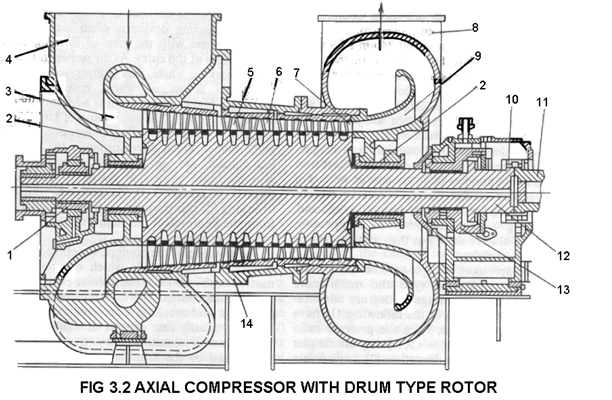
The stage of a compressor can be regarded as an inverted turbine stage. The mechanical energy imparted to the rotor is spent to increase the kinetic energy of the airflow which is then transformed into the potential energy of air pressure. The below image shows an axial flow compressor with a drum type rotor. Compressed air moves from the last compressor stage into
The following are the main components of a typical axial flow compressor.
Comments
Post a Comment